
This is an archive post of content I wrote for the NTDebugging Blog on MSDN. Since the MSDN blogs are being retired, I’m transferring my posts here so they aren’t lost. The post has been back-dated to its original publication date.
Hi, this is Matt from the Windows Performance team. Sometimes we are presented with
problems that defy our usual troubleshooting and require a creative approach. In a recent
case, we needed a way to test the responsiveness of an application as text was typed into its
fields. Initially, we tested the program using a script that used the SendKeys method to time
entry time. Unfortunately, these tests aren’t completely realistic, since the script can be
affected by the processor utilization on the system, and the script can’t create hardware
interrupts like a keyboard does. Realizing that only real keyboard input would be a valid test,
and that the rate of typing needed to be reproduced exactly for each test, I set about building
an automated keyboard.
First, I found an old PS/2 style keyboard that hadn’t been used in years and opened it up.
Luckily, it was old enough to use all through-hole components, which made it easier to modify.
The main component I cared about was the keyboard encoder, which was a COP943C. A search
online turned up a datasheet for the keyboard encoder with a sample circuit design that looked
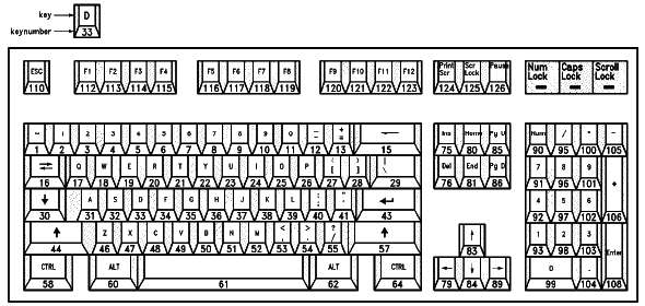
very similar to this keyboard. The document shows there are a couple of steps to determining
which pins need to be shorted to generate a particular key. First, each key has an ID number
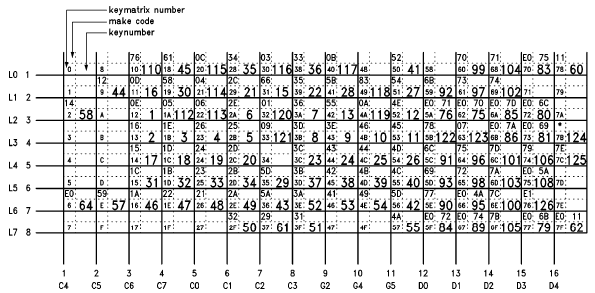
that is shown in figure one of the PDF (figure one below). After finding the proper ID, a table is
consulted to determine the row and column pins used to create that key code (figure two
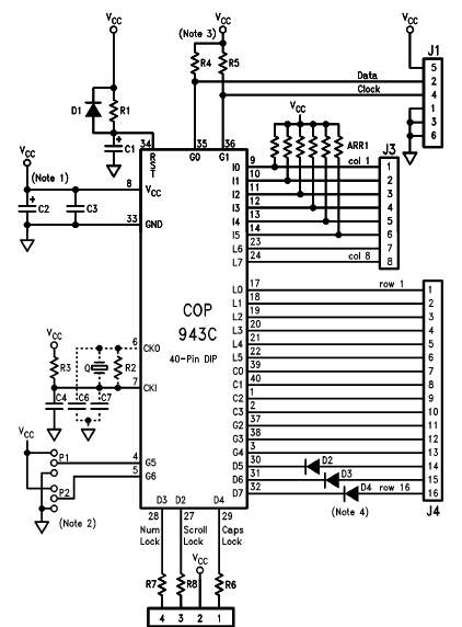
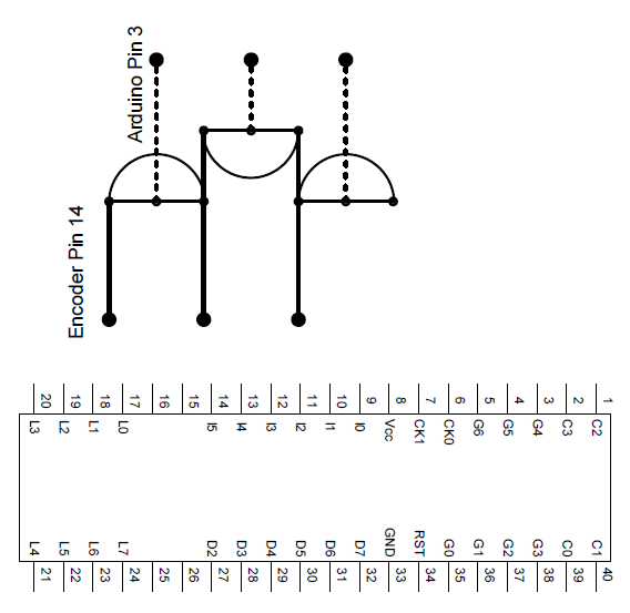
below). Finally, those row and column numbers are translated into physical pins on the
encoder using the schematic diagram (figure three below). For example, the letter ‘a’ is
number 31. The matrix shows 31 is made with the L5 (column 6) pin and C6 (row 3) pin. The
pin out shows this to be physical pins 14 and 19. When tested, shorting these pins creates an
‘a’.
See the Video:
Now that we know how the keyboard circuit works, we need a method to generate key
“presses.” For this, I found a board I assembled a year or two ago using a PCB and components
from moderndevice.com. The board is an Arduino clone that is based on Atmel’s ATmega168
microcontroller. One of the great things about using an Arduino is their IDE, which allows for C
programming with a number of pre-defined functions to make development quick. Also, the
boot loader is already taken care of, which makes the work easier.
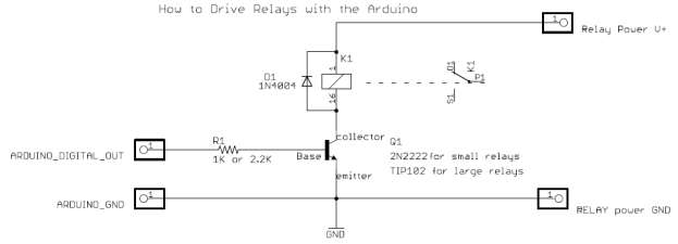
Wiring the board to the keyboard was straightforward. Figure 4 shows how to control a relay
with an Arduino, and triggering a keyboard is rather similar. A resistor is placed between a
digital out pin of the Arduino and the base pin of a transistor. The collector then goes to one
pin of the keyboard encoder needed to type the letter desired, and the emitter goes to the
other pin.
In order to save on solder joints, I decided to chain together the transistors, which affected the
key selection. Additionally, because I wanted to leave the encoder in the original circuit and
some of the pins were blocked by other components (resistors, capacitors), specific pins were
selected. Figure 5 shows the layout of the transistors. These were soldered to a prototyping
board with hook up wire to connect back to a breadboard with resistors and the Arduino and
hook up wire soldered directly to the pins of the keyboard encoder.
These pins selected allowed characters a, s, z, space, and enter to be typed. All that remained
was to write some software to trigger the transistors. The code first sets the digital pins to
output and logic low, turns on a LED to show it is working, then waits 3 minutes to allow time
for the PC to boot and application in question to be launched. The LED then goes out for a five second
warning, and then the loop sequence begins. The loop turns on the LED, types “as z”
followed by enter, then turns off the LED and sleeps for 2.5 seconds before starting again.
// Sample code to drive keyboard encoder
// Matt Burrough
// September, 2008

int ledPin = 13; // Use digital pin 13 for a status LED
int sPin = 3; // Connect pin 3 to the transistor connected to the s leads
int aPin = 4; // Pin 4 is for a
int zPin = 5; // Pin 5 is z
int enterPin = 6; // Pin 6 is enter
int spacePin = 7; // Pin 7 is space
int holdKey = 30; // Milliseconds to "hold" each key down
int betweenKeys = 50; // Milliseconds to wait between key presses

void setup() { // Initial setup code (runs at power-on)
    setupPin(ledPin); // Set up each pin with function below
    setupPin(sPin);
    setupPin(aPin);
    setupPin(zPin);
    setupPin(enterPin);
    setupPin(spacePin);
    digitalWrite(ledPin, HIGH); // Turn on the LED to show the board is on
    delay(180000); // Wait 3 minutes to allow time for PC to boot
    digitalWrite(ledPin, LOW); // Turn off the LED
    delay(5000); // Wait 5 seconds
}

void loop() {
    digitalWrite(ledPin, HIGH); // Turn the LED on
    typeKey(aPin); // Type keys
    typeKey(sPin);
    typeKey(spacePin);
    typeKey(zPin);
    typeKey(enterPin);
    digitalWrite(ledPin, LOW); // Turn the LED off
    delay(2500); //Pause 2.5 seconds
}

void setupPin(int pin) { // Used to set up pins...
    pinMode(pin, OUTPUT); // Set the digital pin as output
    digitalWrite(pin, LOW); // Turn off the pin
}

void typeKey(int pin) { // Type a key...
    digitalWrite(pin, HIGH); // "Press down" on a key
    delay(holdKey); // Hold down the key
    digitalWrite(pin, LOW); // "Release" the key
    delay(betweenKeys); // Pause between keys
}
Figure 6: Code Sample
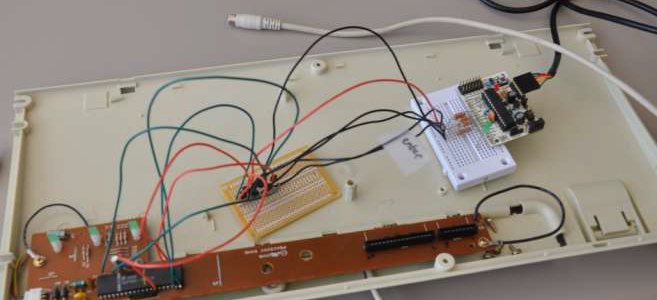
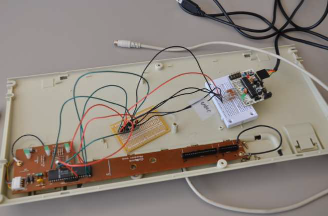
That’s how I made an automated keyboard. I hope that you’ve found this post interesting; I’ll
leave you with a photo of the finished product.
References:
ⁱ http://www.national.com/an/AN/AN-734.pdf
ⁱⁱ http://www.arduino.cc/playground/uploads/Learning/relays.pdf